Loading a 3D model for your Tizen Native application - part 1
PUBLISHED
Introduction
Tizen Native API gives a possibility to create a 3D graphic application based on OpenGL ES 1.1 or 2.0. You can hardcode the model data in the source code and display it (see: Evas GL sample, GLView11Cube, GLViewCube, GLViewShader sample applications in Tizen SDK).
However, don't you think it would be handier to load the 3D model (created with an external tool like Blender) from a file? This will be the topic of this article series.
The first article describes how to export a 3D model from Blender using the OBJ file format and how to understand this format. The second one – how we implemented an example of the OBJ file format parser, which produces arrays necessary to draw the model in a 3D graphic application. Of course, it's a sample parser and its code could be optimized.
Sample application
OBJLoader is a Tizen Native application that displays a 3D model provided as an OBJ file. It uses OpenGL ES 1.1 for this purpose. It's compatible with Tizen SDK 2.3.1.

Sample application screen shot
Attachments
dice.zip– contains a Blender 3D model that we want to load for our Tizen Native application,
dice.png – texture associated with this scene,
OBJLoader.zip – sample application.
How to export Blender 3D model to OpenGL ES 1.1?
There are a couple of ways to do this. In this article we will describe a method using one of the simplest and most common formats to which Blender can export its model – the OBJ file format. So....
… how to export Blender 3D model using OBJ file format?
First, open the “dice.blend” file (attached to this article).
Note: To open a .blend format file you need the Blender software. It's free, open source and can be downloaded from this address.
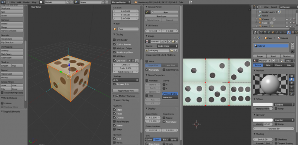
When you open the file, you will see the following view:
Opened dice.blend file
The left window contains our 3D model of dice, the right – its texture.
To export this model select: File > Export > Wavefront (.obj).
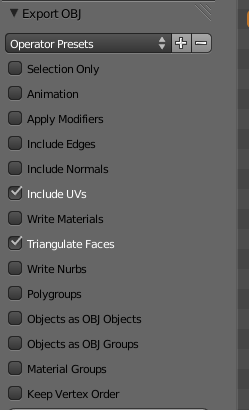
Set the properties of the exported model in “Export OBJ” view as below:

Export properties
We need only two options: “Include UVs” and “Triangulate Faces”.
Next, set the destination folder, filename and click the “Export OBJ” button.
![]()
Done. The 3D model was exported to the dice.obj file.
How to understand the content of an OBJ file?
The OBJ file looks as follows:
# Blender v2.62 (sub 0) OBJ File: 'dice.blend'
# www.blender.org
v 1.000000 -1.000000 -1.000000
v 1.000000 -1.000000 1.000000
v -1.000000 -1.000000 1.000000
v -1.000000 -1.000000 -1.000000
v 1.000000 1.000000 -0.999999
v 0.999999 1.000000 1.000001
v -1.000000 1.000000 1.000000
v -1.000000 1.000000 -1.000000
vt 0.008999 0.504406
vt 0.337549 0.501162
vt 0.337205 0.989883
vt 0.008761 0.994354
vt 0.993876 0.007059
vt 0.992939 0.494500
vt 0.673223 0.496297
vt 0.672896 0.005894
vt 0.990403 0.503104
vt 0.991325 0.991252
vt 0.671281 0.991558
vt 0.673132 0.504406
vt 0.336614 0.499801
vt 0.337796 0.006379
vt 0.668736 0.004828
vt 0.670811 0.500044
vt 0.667237 0.496847
vt 0.667913 0.990515
vt 0.337712 0.988091
vt 0.338190 0.499978
vt 0.337022 0.004075
vt 0.338482 0.498576
vt 0.007316 0.499432
vt 0.007171 0.004682
s off
f 1/1 2/2 3/3
f 1/1 3/3 4/4
f 5/5 8/6 7/7
f 5/5 7/7 6/8
f 1/9 5/10 6/11
f 1/9 6/11 2/12
f 2/13 6/14 7/15
f 2/13 7/15 3/16
f 3/17 7/18 8/19
f 3/17 8/19 4/20
f 5/21 1/22 4/23
f 5/21 4/23 8/24
The first line contains information about a tool you used to export the model.
Lines starting with the letter:
- 'v' means vertex coordinates (x, y, z)
- 'vt' – texture coordinates (u, v)
- 'f' – v / vt data per face
As you can see we have:
- 8 vertices
- 24 texels (= texture pixels)
- 12 faces
Why eight vertices? It's the number of cube vertices, of course. But 12 faces? A cube has six sides. The “Triangulate Faces” option we checked previous causes that every side consists of two triangles. 6 * 2 = 12 faces. Clear?
So, what does “f 5/21 1/22 4/23” mean?
The above line describes which vertices and texture coordinates use to draw one triangle for cube side.
vertex data / texture coordinates
5 → (1.00, 1.00, -1.00) / 21 → (0.337022, 0.004075)
1 → (1.00, -1.00, -1.00) / 22 → (0.338482, 0.498576)
4 → (-1.00, -1.00, -1.00) / 23 → (0.007316, 0.499432)
Ok, we have all the information we need to draw a dice, stored in an OBJ file. We need to transform this information into a form that we can use in our application. And it will be the topic of second article.

